
-
 Pick up from the Roboticshubbd Store
-
 Courier delivery

Arduino UNO R3 x1
LDR Sensor Module x2
2WD- Two Wheel Drive Robot Car kit (includes the acrylic frame, Wheels, BO Motors, Castor Wheel, Screws and nuts, etc.) x1
MX1508 Motor Driver Module x1
9v Battery or 4 AA Battery holder x1
Breadboard Small x1
We’re diving into the hardware side of the Light Following Robot project, and things are getting exciting. Below is the circuit diagram for this project:

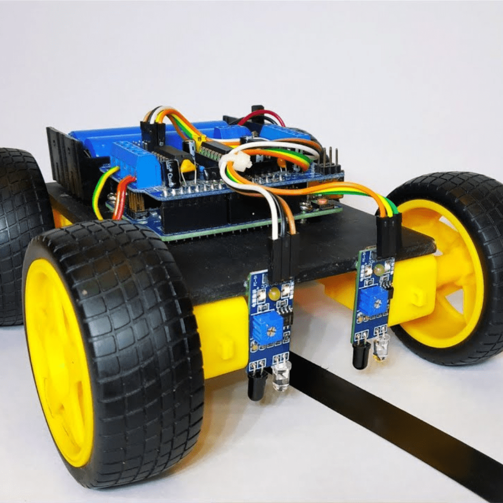
The LDR Sensor Module we’re using has three pins: VCC, GND, and DO. This module outputs a digital signal, which is sufficient for our needs. We connect the DO pins to the digital pins 8 and 9 on the Arduino UNO.
For motor control, we’ve chosen the MX1508 Motor Driver for its simplicity. For more details on Interfacing the MX1508 with Arduino, check out our dedicated article on this topic, which provides all the essential information.
The MX1508 Motor Driver features two control pins per motor: one for forward rotation and one for reverse. Since we only need forward movement, we connect the INT1 pin (forward control for Motor A) and the INT3 pin (forward control for Motor B) to pins 10 and 11 on the Arduino, which also support PWM. This allows us to control the motor speed.
The power inputs for the sensor (VCC & GND) and the motor driver (+ & -) are connected to the 5V and GND pins on the Arduino UNO.

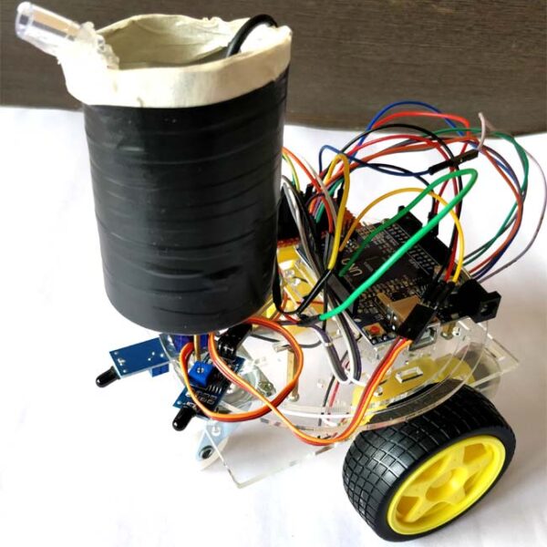
Above, you can see the image of the hardware assembly. Identifying which motor or sensor is on the left or right might be a bit confusing initially. However, this can be clarified through a process of trial and error with both hardware and software.
That wraps up the hardware setup—let’s move on to the coding!
We’ve already discussed the key concepts behind the code, so let’s break down the implementation into two main parts.
Setup Part:
In this section, we define the pins and initialize functions. For this project, we need four I/O pins, which we declare as follows:
#define LeftLDR 8
#define RightLDR 9
#define LeftMotor 10
#define RightMotor 11
// Define the motor speed (0-255)
#define MotorSpeed 255
void setup() {
  // Set LDR pins as input
  pinMode(LeftLDR, INPUT);
  pinMode(RightLDR, INPUT);
  // Set motor pins as output
  pinMode(LeftMotor, OUTPUT);
  pinMode(RightMotor, OUTPUT);
}
Here, LeftLDR and RightLDR are assigned to digital pins 8 and 9 for the light sensors, while LeftMotor and RightMotor are assigned to pins 10 and 11 for controlling the motors. The MotorSpeed variable is used to set the PWM signal’s duty cycle for controlling motor speed. The pinMode function configures each pin as either an input or output as required.
Loop Part:
The loop function contains the logic for controlling the motors based on the sensor readings:
  if (!digitalRead(LeftLDR) && !digitalRead(RightLDR)) {
    digitalWrite(LeftMotor, MotorSpeed);
    digitalWrite(RightMotor, MotorSpeed);
  }
  else if (!digitalRead(LeftLDR)) {
    digitalWrite(LeftMotor, 0);
    digitalWrite(RightMotor, MotorSpeed);
  }
  else if (!digitalRead(RightLDR)) {
    digitalWrite(LeftMotor, MotorSpeed);
    digitalWrite(RightMotor, 0);
  }
  else {
    digitalWrite(LeftMotor, 0);
    digitalWrite(RightMotor, 0);
  }
In this section, an if-else statement is used to determine the motor actions based on the sensor readings:
Both LDRs detect light: Move forward by setting both motors to MotorSpeed.
Only the left LDR detects light: Turn right by stopping the left motor and running the right motor.
Only the right LDR detects light: Turn left by stopping the right motor and running the left motor.
No LDRs detect light: Stop both motors.
This logic ensures that the robot effectively follows the light source by adjusting its direction based on sensor input. Next, let’s upload the code and observe the results.
With all the hardware setup completed, connect the Arduino UNO via USB cable and upload the code.
Powering it might be a bit tricky. You have multiple options like powering the Arduino board using the VIN pin with a voltage greater than 6V using any batteries, powering the Arduino board via DC jack which supports up to 12V, or powering it via USB using a power bank.
To keep it simple, I’m using a 9V battery.
Don’t forget to adjust the potentiometer on the LDR sensor module to set the desired sensitivity of the sensor. With some trial and error, you will find the optimal position on the potentiometer. That’s how I was able to capture the video and pictures in a bright environment.
Above, you can see the working demonstration of the project. The robot successfully follows light, although it’s not perfect due to various factors that I’ll leave for you to explore. If you’re looking to improve this light-following robot, here are some ideas:
Adding additional sensors to increase the detection range of the robot.
Using sensors with analog output can be useful, particularly for controlling the speed of the robot based on the intensity of the light.
Using speed sensors to create a feedback network to adjust the motors precisely.
No account yet?
Create an Account

Reviews
Clear filtersThere are no reviews yet.